

The Contactless velocity measurement principle is quite simple. The most primitive “tool” is your eyes. Every individual can evaluate movement speed by a quick glance through a railway carriage or car window. The brain will process the signal by evaluating distance to a certain object and its angular speed or just life experience. Sensors are used to evaluate the same parameters but with higher accuracy.
First let’s consider laser sensor due to its simpler design. In order to do that one needs to have a moving object, a light source (otherwise nothing can be seen) and an optical system represented by a lens and a photo detector to register reflected signal. Object surface is uneven in terms of color and finish so when it is moving photo detector shall register signal frequency which is proportional to velocity. Typical value of this frequency is defined by a linear size of photo detector registration area and time period required for an object to cross this area. Thus, the task shall be considered as solved, however the accuracy is much to be desired. Optical system registered so-called low-frequency signal. In order to increase measurement accuracy it is required to narrow frequency spectrum generated by a moving object. This can be implemented by a spatial filter (term related to optical raster sensors). Although laser sensor is used to create fringe (interference) pattern, i.e. periodic modulation of object illumination within laser beam (detection area). This is feasible due to laser radiation coherence property because all photons are phased in a beam. Initial beam shall be split in two and re-unite them angle-wise. In this case it will form a spatial filter.
Now any change in object profile or color crossing this structure filter shall generate reflected signal with intensity modulated with the following frequency: illumination period – crossing speed. Signal spectrum is getting narrower depending on the number of generated periods (the more periods, the narrower spectrum). Singular profile or color alteration shall generate not only one pulse but a majority of pulses (pulse group) the number of which is defined by a number of fringe pattern periods. For instance, in practice, beam diameter is 5 mm and fringe period is 0.05 mm will generate 100 beams, and correspondingly pulse groups. Considering that spectrum narrowed approximately 100 times comparing to low-frequency signal mentioned above, this signal is now deficient, interrupting and is called false signal. It shall be noted that usually 20-30 beams is enough to get measurement accuracy up to 0.1% and higher.
In case of optical sensors the object is illuminated by an even light source (a bulb or LED) and periodic texture (pattern) is located inside of the sensor. This creates additional protection to a pattern (a clear example will be sledge vs. bobsleigh), however leading to a lot of issues including frequency response (proportion factor between registered signal frequency and object velocity in Hz/m(m/s) dependency of distance to object. Looking ahead it shall be noted that this problem has already been efficiently resolved.
Detailed analysis of laser and optical velocity sensors operation (spatial filters generation methods, signals processing methods etc.) can be found in monography*. Theoretical part is set forward on two hundred pages. Nevertheless there is no practical guide available for manufacturing of the sensor that shall work in real and adverse conditions (such as major temperature differential, various surfaces or distance alterations during measurement process).
There are a few real contactless sensors manufacturers in the world. There are about 10 manufacturers of laser sensors and less than ten optical sensors manufacturers. In this article we will review sensors of both types fabricated by a Russian company Sensorika-M, LLC. The Company entered the market not long ago so all up-to-date technologies have been used in a process of fabrication for both: hardware and signal processing algorithms. Unique process solutions developed together with leading specialists of the Russian Academy of Science General Physics Institute were involved.
For instance original optical monoblock unit based on wave front beam division principle was used in laser sensor. It provides a stable fringe pattern which is resistant to temperature differential and has zero difference in beam travel resulted in maximum beams setoff range within a broad range of distance to an object. Also no optical block adjustment is required. Optical diagram of the sensor receiving pattern system completely eliminates dependency of measured velocity from an object distance thus preserving high optics illuminating power. Russian and German patents were obtained for this process solution**.
State-of-the-art microcircuits and micro controllers with signal processors are also used for hardware signal processing in receiving analogue electronic products allowing high frequency velocity accurate measurement and implement various output analogue, frequency and digital signals. A wide range of sensors of both types with nominal object distance from 15 to 130 cm and measured velocity range from 0.01 to 100 m/s for industrial application on vehicles is manufactured (see ISD-3 and ISD-5 for detailed description). Laser sensor was registered in the State Register of approved measuring instruments in 2014. Optical sensor is planned to be registered in 2015.
Note that both sensors are measuring mileage (length which is practically required) as per measured velocity (velocity integral time-wise). That said obtainable measurement accuracy (meaning sensor capacity in terms of measurement frequency) has reached its practical limit and actually exceeds required needs. Thus, technical data specifies length measurement accuracy less than 0.1%. However this parameter depends on the length itself and a possibility to check this accuracy independently (as could be seen from examples given below, but actual measurements can be much more accurate). Consequently, the main emphasis shall be placed upon measurements reliability, i.e. equipment shall be free of fault under different conditions and surface types
And a couple more comments related to distance measurement under standard industrial tasks. Let us suppose that there is a long length moving object (metal stripe, glass plate, cloth etc.) which shall be cut in pieces of a certain length. The sensor shall submit a signal to an actuator when this value is reached. Let there is a digital output (Ethernet, USB) that can be used for current measurement length reading. For example, current length data increment (1 m/s)/(0.02 sec) = 2 cm at measurement frequency equal to 50 Hz and object velocity 1 m/s. But this might not be enough. However there is a length pulse output with a ratio 1000 Hz per 1 m/s or 1000 pulse per meter. This output frequency is updated 50 times a second, i.e. measured distance increment shall be equal to 1 mm at any velocity. Obviously this parameter may be set for 10 thousand pulses per meter and in other words length measurement accuracy performed by these sensors is considered as perfect while final accuracy is limited only by specifications of the cutting tool.
Below there are some examples of sensors application with accuracy evaluation and measurement frequenc.
Application test of ISD-5 laser sensor on the road.
Approximate height of sensor installation is 50 cm (allowable limit from 35 to 65 cm). Measurement frequency is 54.2 Hz, velocity measurement range is 0.02–110 km/h. Vehicle with sensors installed on it was moving on a circuit path 1 km long (on urban road, during a sunny day, at ambient temperature –7 ˚С). Vehicle was moving at variable velocity (0–50 km/h) with several stops. Measurement results were defined as per three laps – 1055.740 m, 1056.244 m and 1055.33 m, i.e. measurement frequency was less than 0.05 % considering that the route was not perfectly repeated.

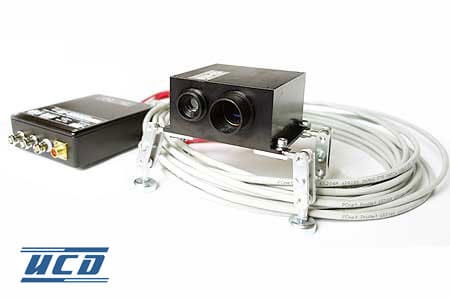
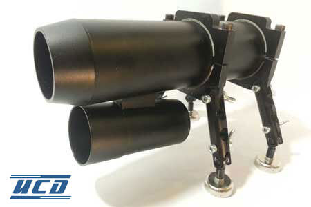
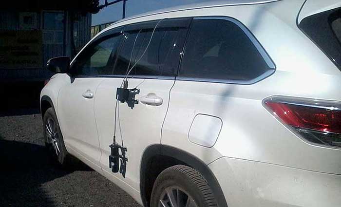
Fig. 1. ISD-3 optical sensor and ISD-5 laser sensor attached to a vehicle for test run
Two sensors, optical and laser were used together. They were attached to a vehicle as shown on Figure 1. Nominal height of ISD-3 sensor installation is at 50 cm from the ground and ISD-5 laser sensor is 130 cm from the ground, but it was installed at 100 cm height. Four laps were taken on a straight section of asphalt pavement (2 laps into each direction) approximately equal in length. After the test relative sensors measurement difference was evaluated. The results are shown in Table 1.
Lap No. | ISD-316, m (measurement 23.6 Hz) | ISD-505, m (measurement 40.6Hz) | Relative difference (V3/V5-1)*100 |
1 | 1345.68 | 1345.01 | -0.05 |
2 | 1394.01 | 1395.08 | 0.07 |
3 | 1382.51 | 1382.73 | 0.016 |
4 | 1345.14 | 1343.06 | -0.15 |
Average relative difference | 0.03±0.1% | ||
Thus, actual measurement quality of both sensors used on the vehicle is equal and relative measurement frequency is basis point. It shall be also noted that optical sensor is more preferable for this type of application because it is more resistant to external negative impacts (temperature, snow, rain), particularly it is considerably tolerant to receiving optics contaminations. This can be compared with a photo camera: even if the lens is dirty one can still take a picture. In the meantime a water drop on a laser sensor optics might result in strong corruption of a fringe pattern on the object.
In order to assess overall measurement quality there is a graph of acceleration/braking speed of a locomotive with goods train shown on Figure 2 (Schsherbinskiy railway testing ground, ISD-3 sensor, nominal distance is 80 cm. Sensor was installed on the bottom of the locomotive and was directed at rails). The graph allows to evaluate instant velocity measurement accuracy because railway cars movement is an example of maximum smooth velocity. Also as an example there are some useful graphs provided for car tires braking tests on ice (performed at the ice ground Arena, in Mytishy, Moscow region with an optical sensor).
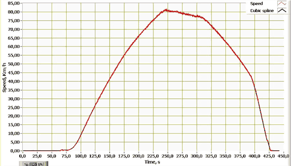
Fig. 2. Locomotive with goods train acceleration and braking velocity diagram
Figure 3а shows five test acceleration/braking runs on non-studded snow tires. Figure 3b shows the same tests but on studded tires. Please note that minor velocity peaks on a graph are not measurement noise, they are real because this is a way a vehicle moves on icy road.
These sensors are widely used in industry as well. Here is one more illustrative example: glass length measurement. The object is a rotating disk made of polished glass with a clean surface. Laser sensor with nominal working distance 130 cm shall be used in this case (in reality glass surface is hot, so measurement shall be done from long distances). A disk has a mark identifying a spot to start and stop circular measurement which is read by sensor. Measured perimeter is 2.173 m. Two sets of 7 and 11 measurements were performed. Average measured length was 2.1732 and 2.1733 m with a regular deviation 0.034 and 0.036% correspondingly.
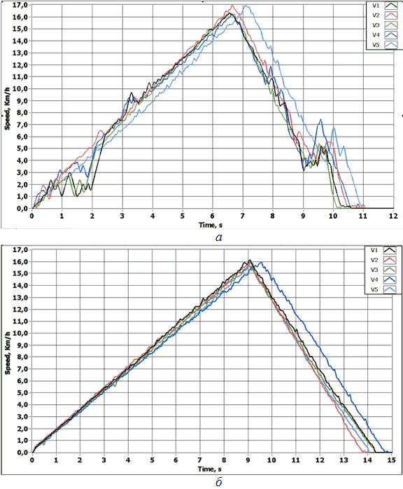
Fig. 3. Accuracy of acceleration and braking velocity measurement of a car on ice obtained by optical ISD-3 sensor: а – a vehicle on non-studded snow tires; b – a vehicle on studded tires.
One of Sensorika-M, LLC recent developments worth mentioning is two-dimensional laser sensors particularly allowing to measure travel speed of a pipe moving on a rolling surface. This shall be practically applicable in insulation shops at pipe mills (serial design will be available starting from second quarter of 2015). Among a majority of unique products one of the most exclusive shall be a sensor able to measure underwater vessels velocity relatively to ambient environment (an experimental model was demonstrated on a forum Russian Marine Industry***). There is a long list of other items but due to a limited scope of this article the only way to get more details is to visit manufacturer’s web-site. In conclusion our contactless distance/velocity sensors are unmatched in valour and sometimes are even better comparing to global analogues but the price is much lower.
_____________________________
* Y. Aizu T. Asakura. Spatial Filtering Velocimetry: Fundamentals and Applications. Springer Series in Optical Sciences. Book 116. 2005.
** RF Patent No. 2482499 and DE Patent 11 2011 102 253 B4.
*** IV International forum Russian Marine Industry held on May 20-22, 2014 in Moscow in Gostiniy Dvor exhibition complex...