
Overview
The main purpose of the Sensor is high precision measurement of speed and traveling distance of the vehicle relative to ground (automotive and railroad application) and speed and length of objects moved relative to the sensor (industrial application).
Measuring principle – raster spatial filtration of an object image, technology is patent pending.
Main features of the ISD-3 family:
- High precision of measurement: 0,03 – 0,1% RMS in industrial, 0,1 – 0,2% RMS of velocity and <0,1% of distance (>100m) in automotive application.
- Reliable measurements on virtually all types of surfaces.
- Broad range of nominal working distances – from 10 cm to 150 cm and it can vary up to 2,5 times during measurements.
- Big lens aperture – geometric aperture ratio up to 1:4. As a sequence, 10 Wt of halogen lamp or even IR diode of 2 Wt electrical power is enough for Electromagnetic compatibility object illumination in most cases
- Low weight and power consumption of controller module (1,5 Wt) due to last generation of ARM microcontrollers used.
Use supply voltage and interfaces indicated in the sensor specifications.
In connection/disconnection of cables, the sensor power must be switched off.
The sensors have been developed for use in industry and meet the requirements
of the following standards:
- EN 55022:2006 Information Technology Equipment. Radio disturbance characteristics. Limits and methods of measurement.
- EN 61000-6-2:2005 Electromagnetic compatibility (EMC). Generic standards. Immunity for industrial environments.
- EN 61326-1:2006 Electrical Equipment for Measurement, Control, and Laboratory Use. EMC Requirements. General requirements.
Currently ISD-3 family included 2 models with different versions with working range from 10 cm up to 100 cm and more. Custom-ordered configurations are possible with parameters different from those shown below.
Coming soon are 2-Dimentional sensors to measure, for instance, longitudinal speed of rotating tubes in tube-rolling mill, or transversal displacement of moving objects.
Although a special version of sensor for road application in automotive testing industry will be available soon.
Main Technical Data
(vehicle application)
Parameters Value Comments Parameter Value Notes Speed range 0,2 – 250 Km/h At TTLout 400 Hz per m/s. Others on request Speed accuracy* <±0,15 % RMS
Determined on test bench (treadmill) at18,38 km/h Absolute distance accuracy* <±0,1 % RMS
After calibration at S >100 m. Measuring frequency 34,5 Hz or 47,5 Hz User ajustable, (max 80 Hz see capt. 10.3. below for details) Nominal distance to the road and tolerance (range of working distance) 35 ± 15 cm or 50 ± 20 cm ** Others on request System power supply (tolerance) 12V nominal (11 – 14,5V)*** System power consumption Sensor head: 20 Wt
Processor unit: 1,5 Wt
Sensor head operation temperature range -20…+50˚С Weight of the sensor + mounting bracket 280g + 120g Without cable Weight of the processor unit 350g Sensor dimensions Ø55 x 205 mm + illuminator See fig.2. Processor unit dimensions 120 x 100 x 35 mm Without connectors Sensor cable length 5 m Up to 10 m on request System power cable length 2 m Up to 10 m on request Environmental sensor head protection IP67 Magnetic fixing tool 4 magnets x 16 Kg strength Option, see fig.2. Controller unit outputs: Analog out
Freuency out
Digital out
Speed, 40 mV/(m/s) 3V max.
Length, 400 pulces/m (=speed 400 Hz/(m/s), meander 0 – 3 V, TTL compatible, up to 200 KHz.
Ethernet (UDP protocol):
No of meas, Speed, Length,
Typical values, user adjustable (see software description below).
DAC and frequency resolution – 12 bit
Others on request
Physical data latency
at measurement freq, ms
34,5 Hz
47,5 Hz
15
11
Stable, =½ of measuring time, without averaging. Base Software - Program to read data via Ethernet, visualization and saving data;
- Program for sensor diagnostics
- Read data example (LabView 8.2.1 and higher);
- Dynamic library (DLL) to read data via Ethernet
- Sensor parameters configuranion via any Internet browther
See below for details.
Custom software by request are possible.
* After calibration on the object to eliminate mounting axes errors.
** For typical road surface. On even and non-contrast surface actual upper limit may be less.
*** Restricted by illuminating lamp only, for it powered directly from power supply. Processor unit and sensor electronics has an individual +5V linear regulator with up to 35 V tolerances.
Due to our continuous efforts to improve sensors, Riftec reserves the right to change specification without prior notice.
Example
Example of item designation when ordering
ISD – 3 – 30cm – ET+232+CAN – AN(U) – PL – 5m
Symbol Description 35cm Nominal distance to the object ET+232+CAN Digital interfaces:
ET - Ethernet – base, other - options:
232 or 485– RS232 (485),
CAN – to avoid any discrepancies the data format of client DAQ needed
AN(U) Analog out, voltage (U) – base - or current (I) PL Pulce out – base 5m Cable length from sensor to controller unit System Parts and Connections
System parts and connections are shown on fig.1 below.

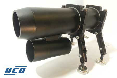
Fig. 1. Sensor parts and connectors.
At +5V on “Stop Count” on no pulces on TTL out. It is used when there are long stops mowing to avoid false reading in length
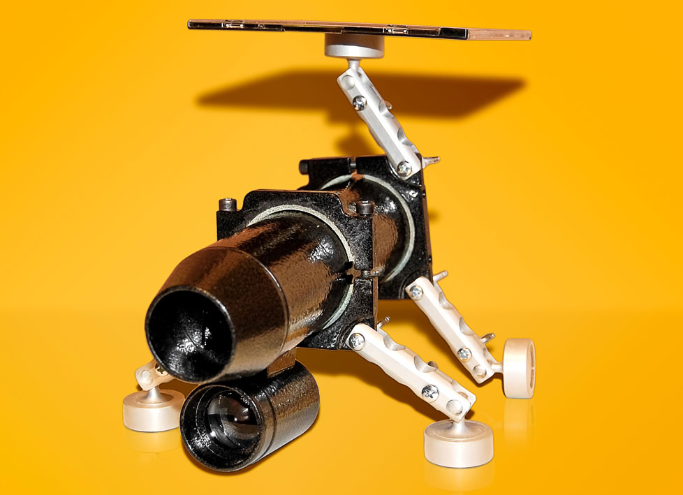
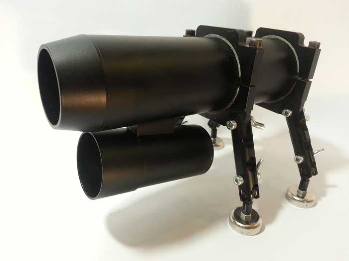
Gallery