
Overview
Laser speed and length sensors are intended for industrial application in metallurgy, cable production, textile fabrics etc.
Measuring principle – Laser Doppler interferometry (reflected type) for direct speed measurement and length calculation based on speed integration.
Industrial applicanions:
- Precision speed and length measurements of finite or infinite moving objects relative to fixed sensor.
- The sensor can be fixed on moving object ( crane, electric loader etc.) to measure its speed and displacement relative to ground
Main features:
- Precision measurements: up to 0,02 – 0,1 % RMS of speed and <0,05% absolute length (>1m).
- Reliable measurements on virtually all types of surfaces, including glass.
- Broad range of nominal distances: 10 – 100 cm and more.
- Original monolithic beam splitter forms stable interferometric pattern, and provides the bigger distance tolerance among such sensors – up to ±25% of nominal distance.
- Thermo compensated design provides temperature independent measurements, no thermo stabilization needed in broad temperature range*.
- Low power consumption of sensor head (0,5 – 2 Wt depends of laser power needed) and controller module (1 Wt).
*No temperature drift in +15…+50С range. At lower temperatures thermo stabilization of housing can be used.
Use supply voltage and interfaces indicated in the sensor specifications.
In connection/disconnection of cables, the sensor power must be switched off.
The sensors have been developed for use in industry and meet the requirements
Of the following standards:
- EN 55022:2006 Information Technology Equipment. Radio disturbance characteristics. Limits and methods of measurement.
- EN 61000-6-2:2005 Electromagnetic compatibility (EMC). Generic standards. Immunity for industrial environments.
- EN 61326-1:2006 Electrical Equipment for Measurement, Control, and Laboratory Use. EMC Requirements. General requirements
The sensors correspond to the following laser safety classes according to IEC 60825-1:2007
Model of the sensor ISD-5 Standard Wavelength, nm 635, 660, 808 Output power. mW 5 - 120 Laser safety class 3В
Class 3B sensorsIn ISD-5 Standard c.w. semiconductor visible range lasers 5 – 20 mW or IR up to 120 mW (for longest working distance) are used. They belong to 3B laser safety class. The following warning label is placed on the laser body (as an e[ample):

The following safety measures should be taken while operating the sensor:
- Do not target laser beam to humans;
- Avoid staring into the laser beam through optical instruments;
- Mount the sensor so that the laser beam is positioned above or below the eyes level
- Mount the sensor so that the laser beam does not fall onto a mirror surface;
- It is recommended to use protective goggles while operating the sensor;
- Avoid staring at the laser beam going out of the sensor and the beam reflected from a mirror surface;
- Do not disassemble the sensor;
- Use the protective screen mounted on the sensor for the bocking of the outgoing beam:
Class sensors 3R
In ISD-5 Standard c.w. semiconductor visible range lasers <5 mW are used. They belong to 3B laser safety class. The following warning label is placed on the laser body (as an e[ample):

The following safety measures should be taken while operating the sensor:
- Do not target laser beam to humans;
- Avoid staring into the laser beam through optical instruments;
- Mount the sensor so that the laser beam is positioned above or below the eyes level;
- Mount the sensor so that the laser beam does not fall onto a mirror surface;
- Use protective goggles while operating the sensor;
- Avoid staring at the laser beam going out of the sensor and the beam reflected from a mirror surface;
- Do not disassemble the sensor;
Currently ISD-5 family included 2 models with different versions with working range from 10 cm up to 100 cm and more. Custom-ordered configurations are possible with parameters different from those shown below.
Coming soon are 2-Dimentional sensors to measure, for instance, longitudinal speed of rotating tubes in tube-rolling mill, or transversal displacement of moving objects.
Although a special version of sensor for road application in automotive testing industry will be available soon.
Main Technical Data
Parameter ISD-5 Standard Notes Speed range, m/s 0,02 – 20 Typical values. The less nominal working distance the less min and max speed range. Speed accuracy*, % RMS ±0,07
±0,02
No signal averaging
With averaging 0,2 - 0,3 s,
at V > 1 m/s
Length accuracy*, % RMS <±0,05 При предварительной калибровке на длинах пути >2 м. Measuring frequency, Hz 16 - 54 Nominal distance to the object (tolerance), сm 10, 20, 30, 50, 75, 100) Could be noted at ordering Distance tolerance ±20-25% of nominal Depends on the surface ( on the edge of the range signal decreased) Emitter type Visible or IR c.v. laser, 5 – 120 mW class 3B – 3R Power supply, V 12 (8 - 14 ) Internal linear voltage regulators +5V in sensor and controller unit. Power consumption, Wt:
Sensor
Controller unit
0,5 - 2
1 Temperature working range, С +15...+50 -10…+50 – with active thermostabilization (option): -50..+80С with protect air cooling housing (option). Sensor weight, g 320 Sensor size, mm 85х79х46 Without connector , blend and fixing holes (see picture below) Cable length from sensor to controller unit, v 1,8 or 3 Standard cable RS-232 or VGA with DB9 connectors are used. To extend a length it is possible to connect cables sequential. Sensor environmental protection IP67 Controller unit: Weight, g
Size, mm
350
120х100х35
Analog out
Freuency out
Digital out
Speed, 150 mV/(m/s) 3V max.
Length, 2000 pulces/m (=speed 2000 Hz/(m/s), meander 0 – 3 V, TTL compatible, up to 200 KHz.
Ethernet (UDP protocol)
Typical values, user adjustable (see software description below).
ADC and frequency resolution – 12 bit
Others on request
Physical data latency
at measurement freq, ms
54 Hz
16 Hz
9
31
Stable, of measuring time, without averaging. Base Software - Program to read data via Ethernet, visualization and saving data;
- Program for sensor diagnostics
- Read data example (LabView 8.2.1 and higher);
- Dynamic library (DLL) to read data via Ethernet
- Sensor parameters configuranion via any Internet browther
See below for details.
Custom software by request are possible.
*Precalibration needed to reject the geometric errors of sensor mounting.
Due to our continuous efforts to improve sensors, Riftec reserves the right to change specification without prior notice.
Example
Example of item designation when ordering
ISD – 5.[1 or 2]– [x]cm – [ET or USB ] – AN(x) – PL – SM – [x]m – H – P
Symbol Description St St – Standard x cm Nominal distance to the object ET or USB Digital interfaces:
ET - Ethernet interfaces
or
USB - USB 2.0 interfaces
Simultaneous installation of two interfaces is not possible!
AN(x) Analog out, voltage (U) – base - or current (I) PL Pulce out – base SM Measurement Stop Function x m Cable length from sensor to controller unit, m Н Sensor with in-built heater [heat stabilizer] - option Р Sensor with protect air cooling housing - option System
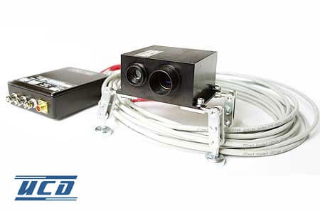
System parts and connections are shown on fig.1 below.
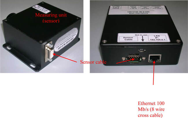

Fig. 1. Sensor parts and connectors.
At +5V on “Stop Count” on no pulces on TTL out. It is used when there are long stops in object (cable, for instance) mowing to avoid false reading in length.
Overall and mounting sensor dimensions

Fig.3. Overall and mounting dimentions of ISD-5 Standa.